I sat down Thursday night and really gave some thought on how to switch the Mojo Critter on/off using the momentary AUX output. I ended up giving up on the relay idea because it would draw too much power. Eventually, I came up with a little circuit using a transistor to switch the decoy on and off that runs on the 6V supply of the decoy and draws very little power. I went to my electrical engineer friends house yesterday and got some components to build the circuit (as well as a review of and some adjustments to my circuit design). I built the circuit on a prototype board to test it out, and it worked perfect! Here is a picture of my test circuit.

I didn't have to cut any wires to connect it into the decoy's wiring. The circuit can easily be removed from the decoy wiring so the decoy can be used as stand alone. Next, I need to try and fit the circuit into the decoy itself or into its own little enclosure. If I put it in it's own enclosure, then it should be able to control other decoys. I'm not sure how the batteries connect in the Mojo Woodpecker, but if it is the same as in the Mojo Critter, then it could control the Woodpecker decoy, as well. Maybe somebody with the Mojo Woodpecker could let us know.
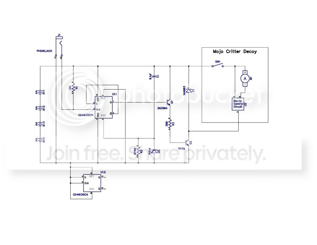
I don't have anything but a messy hand drawn schematic, but if people are interested, I could try and make up a nicer schematic to post.
I didn't have to cut any wires to connect it into the decoy's wiring. The circuit can easily be removed from the decoy wiring so the decoy can be used as stand alone. Next, I need to try and fit the circuit into the decoy itself or into its own little enclosure. If I put it in it's own enclosure, then it should be able to control other decoys. I'm not sure how the batteries connect in the Mojo Woodpecker, but if it is the same as in the Mojo Critter, then it could control the Woodpecker decoy, as well. Maybe somebody with the Mojo Woodpecker could let us know.
I don't have anything but a messy hand drawn schematic, but if people are interested, I could try and make up a nicer schematic to post.
Last edited: